DX 50 MHz Beacon description - preliminary, under development!
The design uses Atmel AtMega8 controller (16 MHz version) to control 50 MHz propagation beacon - PLL control and morse keying generation (possible both CW or FSK). AVR code written in assembler, using AVR Studio.
PLL control
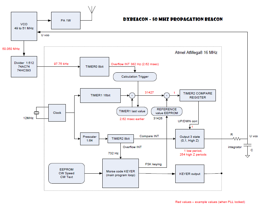
PLL is responsible for frequency control of VCO (in this example the VCO locked frequency is 50.050 MHz).
The VCO output is divided by 9 bit binary counter (realized as 2x2x128 = 512, using 74AC74 and 74HC393). That means the divider
output frequency is 97.754 kHz (must be bellow CPU clock freq). The divider output is connected to 8 bit T0 timer
that generates an interrupt every 256th tick (381.85 Hz, period 2.6188 milisec).
The CPU clock frequency is 12 MHz. The clock signal is feeded directly to 16 bit counter T1 without
prescaler. That means during one T0 cycle counter values changes by 31426. This change is taken as a reference
to generate PLL voltage (if the change is higher that means the VCO is operating on lower frequency and it is
necessary to increase VCO voltage; if the change is lower the voltage must decrease; if the value is exact the
frequency is correct and no change is necessary). If the reference number is changed by 1, the VCO lock frequency is
1592.6 Hz (channel spacing).
In order to realize smaller FSK shift than one channel spacing unit a "cycle jump" method is used. Every N-th cycle
the reference value is just for that particular cycle increased by one, resulting (after PLL filtering) the freq
to change by channel spacing/N, for example when N = 4 the shift is about 400 Hz. There is just danger that freq
can cause parasitic FM modulation to the signal when VCO voltage filter is not efficient.
The T2 counter is employed to realize VCO voltage control. It is a 8bit counter. It uses internal prescaller 64 with system clock 12 MHz resulting in period of 1.3653 msec (732 Hz), approx.
half of the value (double freq) than PLL cycle.
The frequency deviation (absolute value) we got as an offset of T1 timer and
reference value generates a number that is fed into T2 timer and it determines the duration of voltage correction;
the "polarity" of correction pulse is determined by deviation sign. Note: the T2 timer is 8bit only, so when the
deviation is more than 255, it must be limited to 255 only! That can cause problem only when we need very fast
frequency jumps - it can take longer than another PLL systems (but it is no problem for beacon type VCO when the
freq is stable without request for large fast hops; the longer locking time during power up is also acceptable).
The output is realized by 3 state CPU digital output: when the output is set to HIGH it means the increase of VCO
voltage is necessary (tune UP command), when the output is LOW the integrator voltage goes DOWN (VCO tunes DOWN),
when the output is in HIGH IMPEDANCE state the correction is not necessary. That means the VCO voltage range is from
0V to Ucc, in fastest tuning rate (VCO far from lock freq) the output is 0V or 5V all the time, the minimum
correction signal has a factor 1:256. The maximum correction signal is reached when the frequency offset is greater
than 400 kHz. The correction signal is generated every cycle when the deviation is
more than 1.6 kHz (for 800 Hz deviation the signal is active every 2nd cycle etc.).
IMPORTANT - the VCO oscilator MUST generate signal all the time, no matter what PLL voltage is. Otherwise PLL loop stops working!!
Morse code generation
The beacon transmits the morse code message stored in EEPROM. The timing of the message uses the T0 timer with stable
clock cycle (enough for CW). The keying is possible by both methodes: A1 and F1. For A1 system switch off the
"small FSK shift feature", for F1 system select "small FSK shift" N parameter and keep the carrier on the whole time.
The morse message is fixed text (usually beacon ID, location etc.) but some telemetry can be easily added in later versions (?).
The character (byte unit) uses 1 flag bit (it is a morse character or control character) and 7 data bits.
The EEPROM capacity 512 bytes is sufficient for long enough message (current version - only about 200 chars available).
Timing of morse code is based on TIMER 2 - interrupt period 1.3653 msec. The dot length is multiple of this period,
the speed constant in placed in EEPROM. The text is stored in EEPROM in form 1 byte = one character, coded 0 = dot, 1 = dash, leading 1.
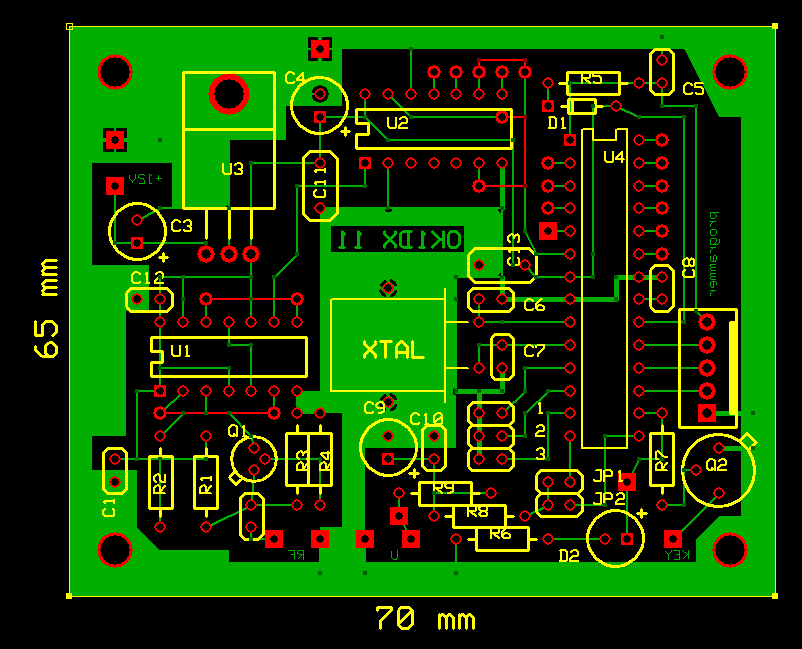
Circuit diagram - Controller
All sources
73 OK1DX