DXVFO - CW Transceiver VFO (variable frequency oscillator) project
Last update April 3, 2016
Design of cheap VFO, based on widely available parts. Non commercial Hamware project. I know that there are many similar projects available (but not all of them as Hamware), it is just a challenge to build an own one. Intended to be used in small CW HF QRP homebrew transceiver project (Jirka OK1DXK is working on analog block design). But it can be used also as independent parts only (elbug, HF DDS generator, VFO for SSB transceiver...). The heart is Atmel AtMega8 controller, frequency is generated by AD9850 DDS (optionally AD9833). AVR code written in assembler, using AVR Studio.
The inspiration came from the fact that cheap and powerfull parts are available nowadays (mostly on Ebay) that can be used to build a VFO that fulfils higher requirements than that used in QRP radios in the past. I have tried to avoid SMD parts as much as possible to make contruction more friendly for ordinary HAM.
Project status: all features implemented, RF output OK. To be tested in real transveiver / real operation on air. PCB is expected to be slightly changed for final release.Use on your own risk! :-)
Features
TX oscillator frequency up to 30 MHz with AD9850 / 125 MHz clock (no mixing necessary), high stability (based on DDS clock oscillator), can include IF shift as well (activated by macro in code) - default no shift.
RX oscillator frequency selection possible above/bellow the band, configurable for each band iseparately, IF frequency configurable (in EEPROM)
Up to 16 different frequency bands, configurable band borders
Split operation inside one band supported (2 VFO system)
Independent RIT control (separated potentiometer), always active
Manual tuning using incremental encoder (prototype model - 3 kHz per turn, 2 Hz step), faster tuning step by fast rotation
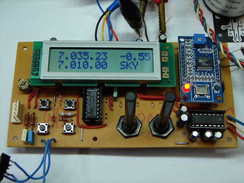
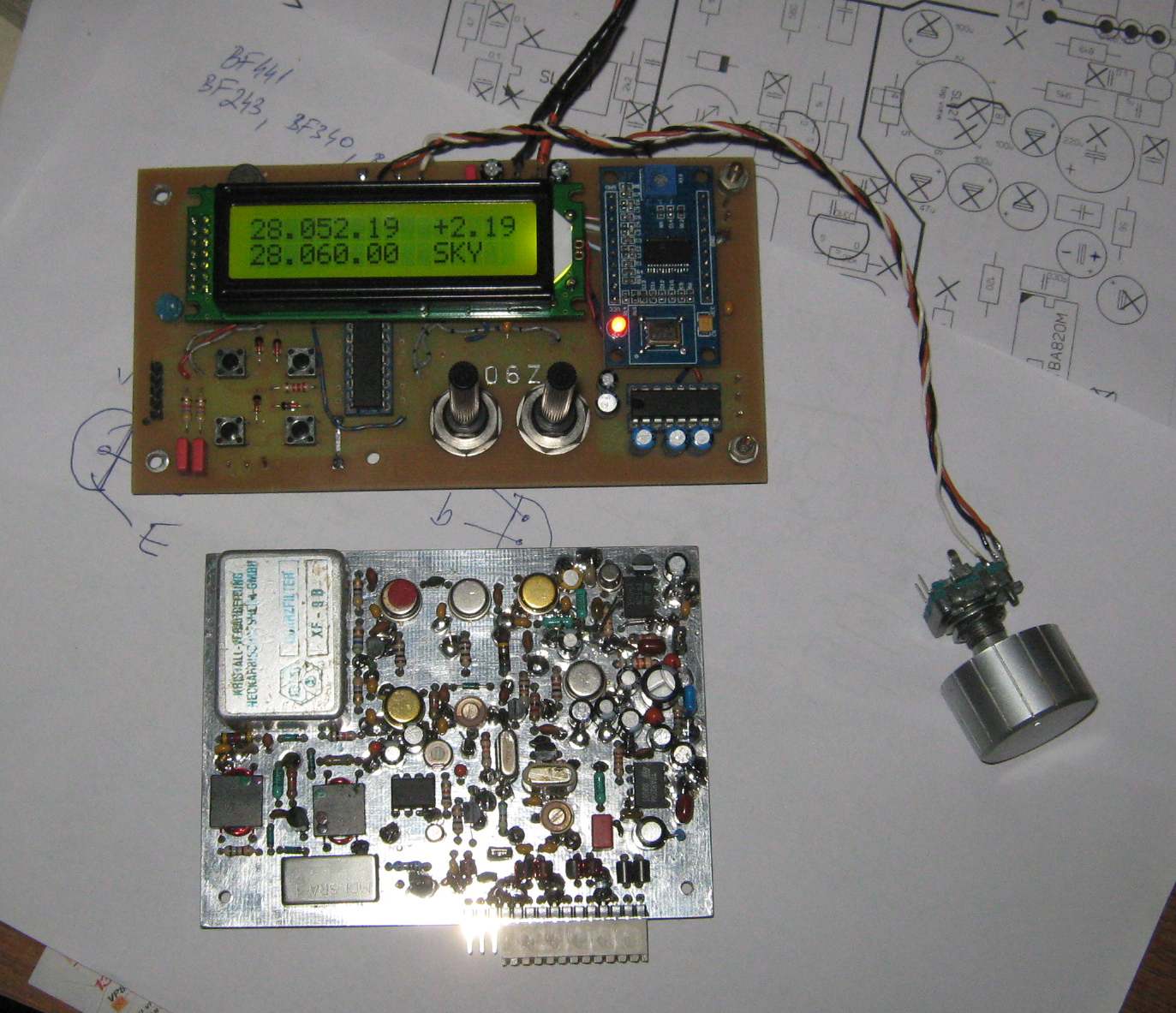
LCD display 2x16 characters, indicating main VFO frequency, split VFO frequency, RIT offset, split status, elbug status and elbug speed, CAT activity
Build in squeze elbug (paddle polarity configurable by pannel buttons, straight key mode supported), speed controlled by independent potentiometer
CAT computer control using RS232 signal levels (or possibly USB adapter), implemented basic Kenwood TS850 instruction format
4 control buttons: A/B, A=B, SPLIT, BAND.
The frequency of VFO is saved into EEPROM by band switching (for each band separately)
Last band and elbug mode selection is stored in EEPROM as well in order to avoid not necessary operation after next "power on"
hardware binary outputs that can be used to perform band switching inside the transceiver analog part.
Processor can be programmed "in circuit" using dedicated connector
Configurable parameters are stored in EEPROM (like band borders, elbug speed range, DDS clock frequency, RIT range,...)
Hardware description
Controller chip is Atmel AVR AtMega8 running at 12 MHz. It is not the latest model, advantage is it is widely available in DIL package and it is cheap. Of course, if necessary, some newer AVR chip can be used as well with minimum effort for porting. But Mega8 can still fulfill its duties as needed, and there is still enough space to extend the program (flash memory 50% full).
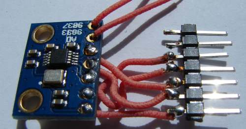
The oscillator signal is generated by Analog devices AD9850. DDS chip AD9833 is supported as well (lower consumption, frequency only up to about 10 MHz / 25 MHz clock). Also, it is not the latest AD model, but well known and available. It is SMD part, but fortunatelly complete modules (including output filter) are available from China on Ebay for resonable price.
CAT interface uses well known MAX232. If you don't need it, just don't use it. You can also try to connect widely available USB to TTL serial adapter and connect it to CPU directly.
LCD display is connected in 4bit mode, write only mode (in order to spare pins). So there is no pooling for display readiness, time delay is used instead. One advantage - the program is not affected when display is not connecter or is not working properly.
Elbug speed and RIT is realized by analog potentiometers, voltage is connected to internal analog to digital converted inside AVR.
Band data outputs (can be used to control band switching) are realized by external 74175 register, in order to save AVR pins.
Latest firmware version is 1.2 (added support for AD9833, fast tuning, fix RX freq when band bellow IF freq). Note: check the switch in the source code when you need to compile program for different DDS chip!
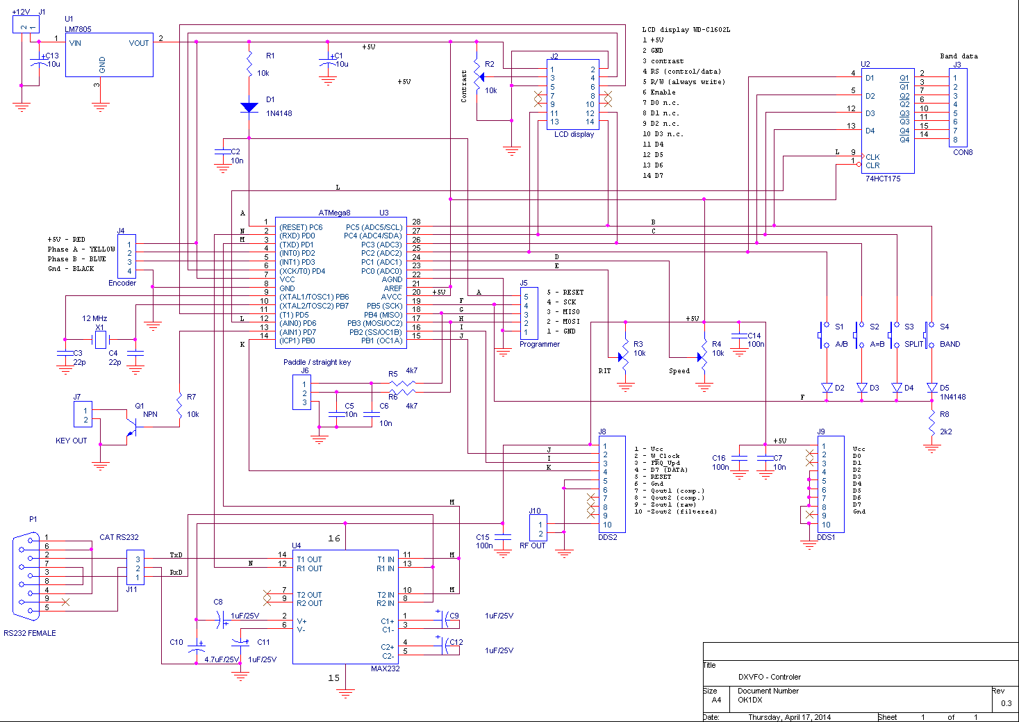
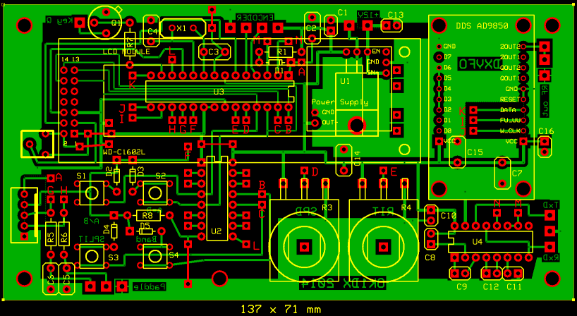
Mainboard diagram
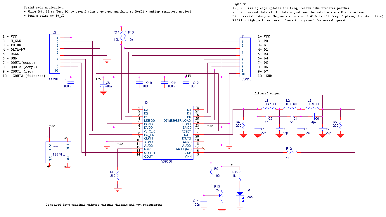
DDS module AD9850 circuit diagram
DDS module AD9833 circuit diagram
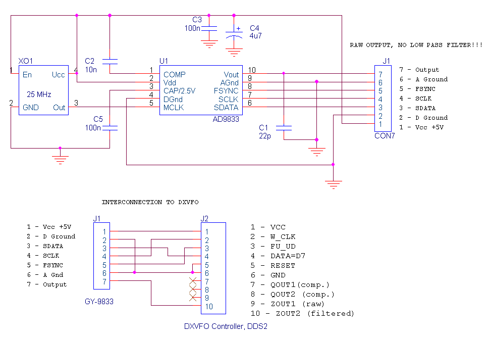
Module GY9833 with test interconnection
Parts availability:
DDS module AD9850 - eBay price from China $10
Incremental rotary encoder (400 pulses/revolution), robust version - eBay price from China $14
Atmel AtMega8 16PU - around $2
LCD display - everywhere around $5
Expected total component price bellow $50
Firmware description
The basic requirement is the controller must react very fast to 2 things: frequency control by knob tuning and elbug. The other things (display control, CAT,...) are not so important and must not delay that 2 functions above.
Encoder handling is realized as interrupt procedure and therefore it is very fast. Interrupt is used also for timing - one timer for elbug timing and the other as general timer. But rest of the program is performed in main loop, including things like elbug logic and sending data to DDS module. So the main loop must be also very fast, without any kind of waiting loops. This is especially important for LCD control and serial port control (CAT). The problem is solved by buffers - one for LCD, two for CAT (RX queue and TX queue).
There is a common data bus used for LCD data, control buttons and band data.
The processor sends data to DDS based on RX-TX mode (by TX it generates directly required TX frequency, by RX frequency with IF offset). In order to avoid clicks by TXing, the TX frequency is set immediately, but switching to RX is performed by short time delay, to avoid falling signal edge to be well shaped. See comments in source code for more details.
The program has been completely written in AVR assembler, can be compilled by AVR studio (available for free). You can find the sources and binaries at this page, you can download them and use for non commercial purposes for free (Hamware). You can modify the sources as you like, just please keep indication of origin. Commercial use only with author's approval!!!
Prototype PCB design (lot of wire jumpers)
DXVFO made by 4O6Z
Project files
73 OK1DX