Low Pass Filter 2m
The filter should be connected to power amplifier output in order to reduce amplitude for unwanted harmonic products.
So there are 3 requirement:
attenuate frequency products above limit frequency as much se possible. There should be a maximum attenuation between input
and output connectors, expressed in dB.
minimum attenuation of required signal, in order not to lose the valuable power.
the filter should be able to handle the power up to required limit.
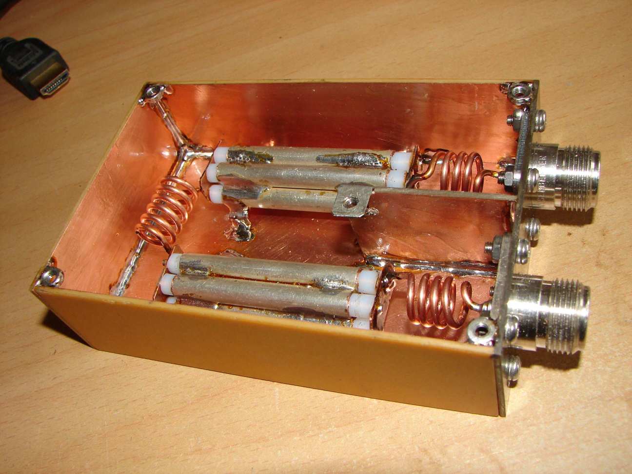
There are many different designs, I don't want to make a cookbook for another one. So perhaps the pictures give ideas for you
own constructions.
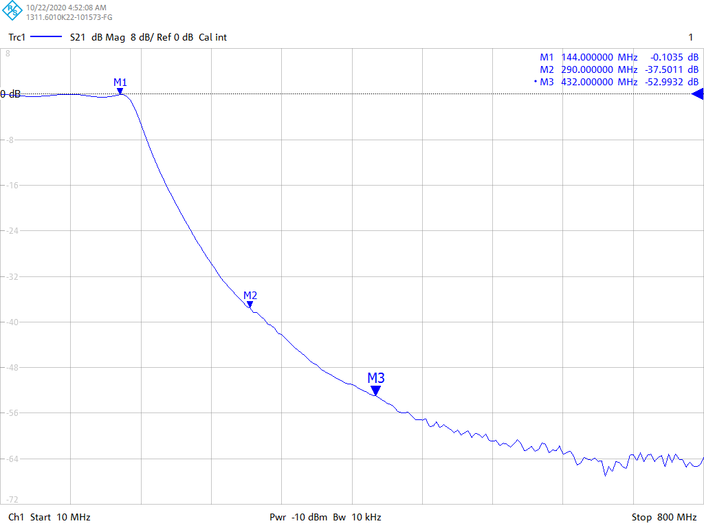
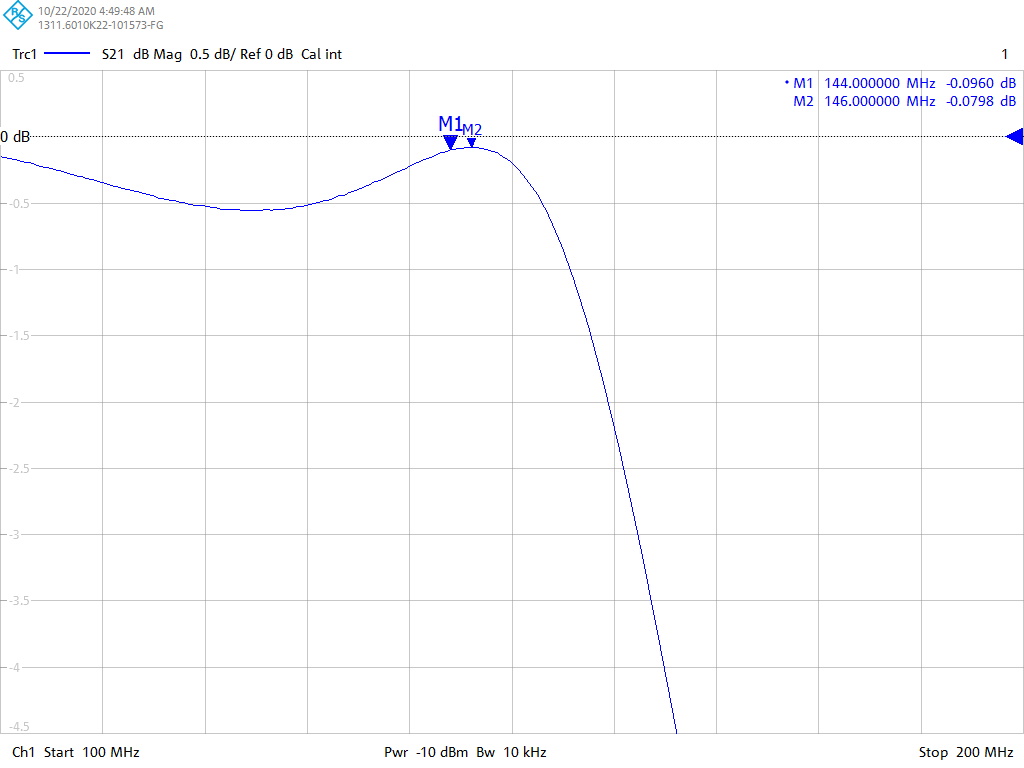
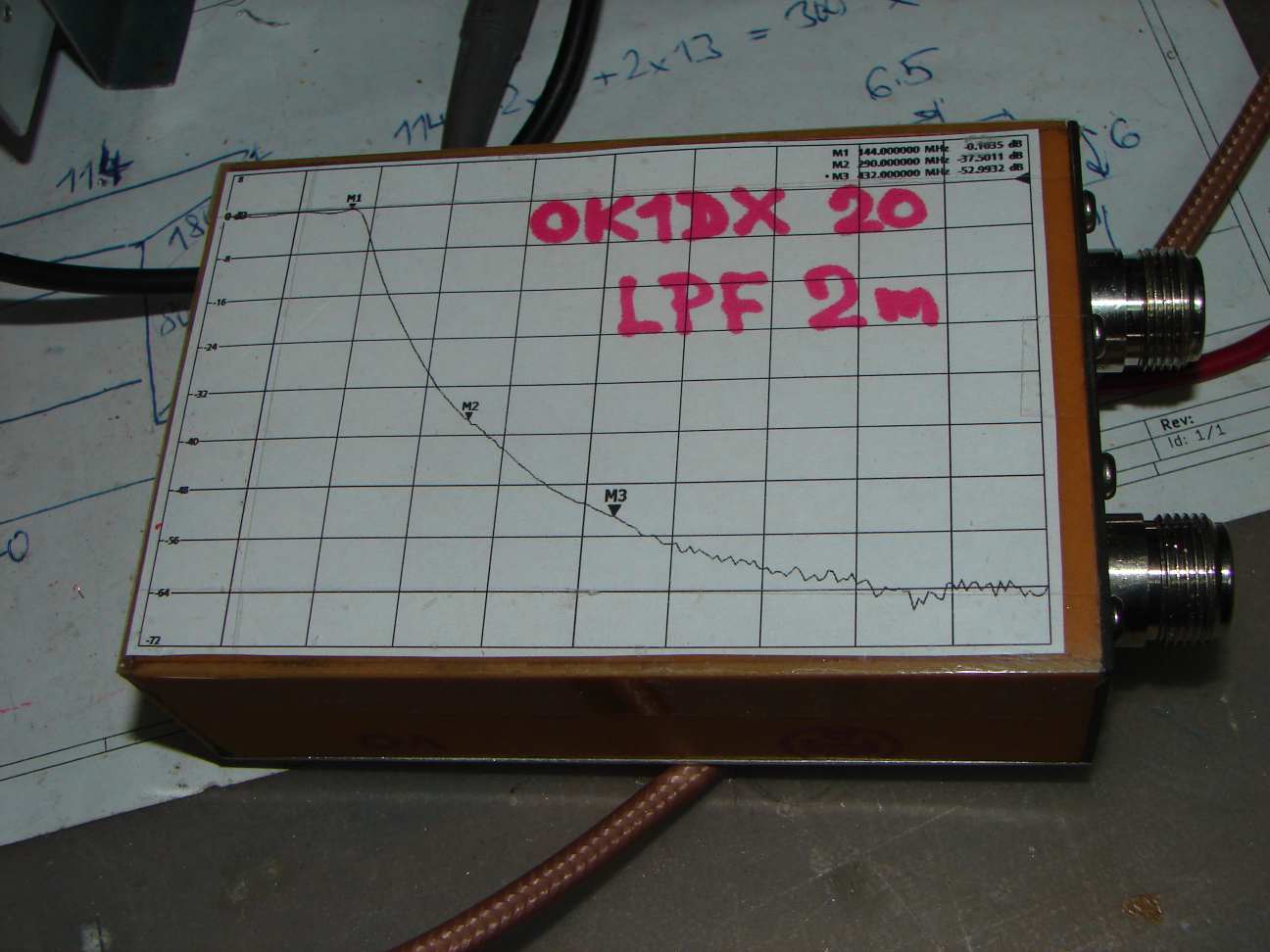
The paramaters are: passband attenuation (144 to 146 MHz) 0.1 dB, 2nd harmonic attenuation 37 dB, 3rd harmonics (70cm band) 53 dB,
power handling at least 500W.


The coil design is usually quite simple and clear, but capacitors are critical. Someone use special ceramic types, other possibility
is use pieces of high quality double sided PCB material (PTFE). In my case there are segments of 50 ohm teflon hardline coax cable internal
dia 7mm. Such cable has a capacity about 1pF/1cm, so for 25pF capacitor I use 5 pieces, 5 cm each. It is not easy to solder because
of good thermal conductivity of copper pipe. Don't forget safety insulation air gap, esp. at corners. There can be easily a
voltage in kV range, esp. in unmatched state, and air has a limited dielectric strength. The picture is better than long speach.


