GPS controlled 10 MHz Reference Generator
Last update October 3, 2019, version 1.0
A relatively simple reference generator for laboratory use or as clock reference for different PLL generators.
Features
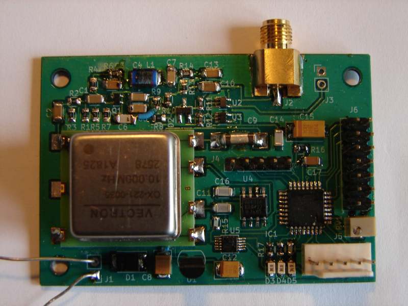
It uses commercial OCXO (oven controlled crystal oscillator), that guarantee frequency stability and signal purity (significantly better than standard XO or TCXO)
The penalty for that is higher current consumption (heating) and longer time needed for frequency to settle.
It can use PPS (pulse per second) signal generated by GPS receivers to automatically adjust OCXO frequency through 12bit DAC converter (lock on GPS standard).
To get clean signal the reference voltage source for tuning voltage uses dedicated reference voltage IC.
When the PPS signal is not available, it uses latest adjustment value (once synchronized, the tuning voltage value is stored in EEPROM).
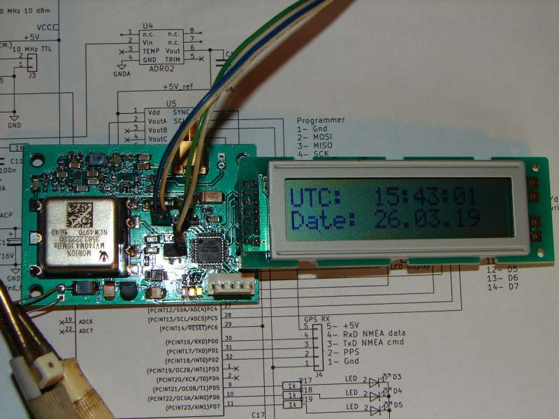
Additionally a GPS NMEA data stream (9600Bd 8N1) can be connected to the RefGen, the processor extracts some information (date, time, coordinates) and display them on LCD display.
The LCD display (2x16 chars model, HD44780 compatible) is optional (can be removed).
LCD display shows cyclicly screens: coordinates, UTC+date, actual DAC value and EEPROM status (value read, writen or same as in EEPROM), actual pulse counter difference, WW Locator and up time.
There are 2 outputs: sine wave level about +6dBm, and square TTL level.
There are 3 LED's on board - one indicating valid PPS signal, one for frequency correction down and one for correction up (action of PLL).
Processor can be programmed "in circuit" using dedicated connector
Firmware of Atmega88 MCU is written in C (using free WinAvr toolkit and libraries) and free available (but still under development).
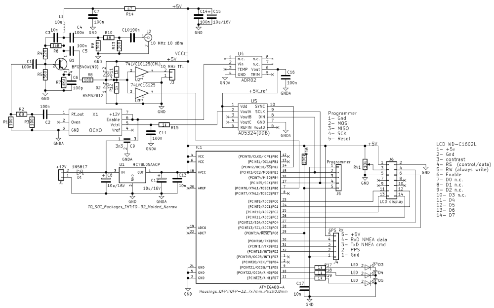
The circuit diagram and PCB layout is done in KiCAD and included.
Hardware description
The OCXO 10 MHz output is used also as clock source for MCU. The frequency measurement is done using 8bit counter (overflow is not necessary to be handled), the counter is sampled by edge on PPS input.
12 bit digital to analog converter (DAC) sends a voltage used for OCXO tuning correction (typical OCXO has a sensitivity 1ppm/V, that means the tuning range is +/- 25 Hz, that is highly precise itself).
Based on result (freq lower or higher) the DAC value is updated in required direction in order to minimise the difference. Once a stable value is found (minimum variation of DAC value),
the DAC value is written into EEPROM for further startup. As a result 1 bit step of DAC corresponds about 12 mHz (miliHertz) frequency step, or in other words, one more 10 MHz pulse every 1.5 minute.
To prevent confusion of PLL loop when OCXO is not fully heated, the PLL is blocked for about 2 minutes after power up.
The LCD display works in 4bit no response mode (MCU just writes into LCD, no reading back). So the LCD can be removed without side effect.
The RxD input of MCU is used for NMEA data. The LCD can then show not only status of PLL but also actual time, date, coordinates and WW locator (maidenhead). The GPS module used for testing is
NEO-7M, available on eBay.
Actuality
I still have several PCB's available (the manufacturer prepared 10 pcs, more than I needed), so I offer the remaining PCB's to those with serious interest for free. Just one detail -
there is missing ground connection by R9, use wire jumper. The KiCAD files are corrected already.
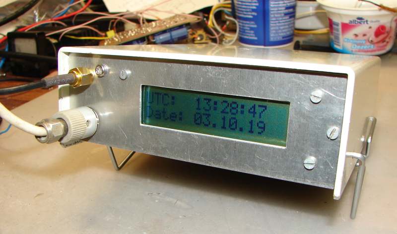
Running with LCD
RefGen circuit diagram
Complete with GPS module NEO7/external antenna and power supply (LM2491 for RefGen and separate 78L05 for GPS receiver - about 70 mA)
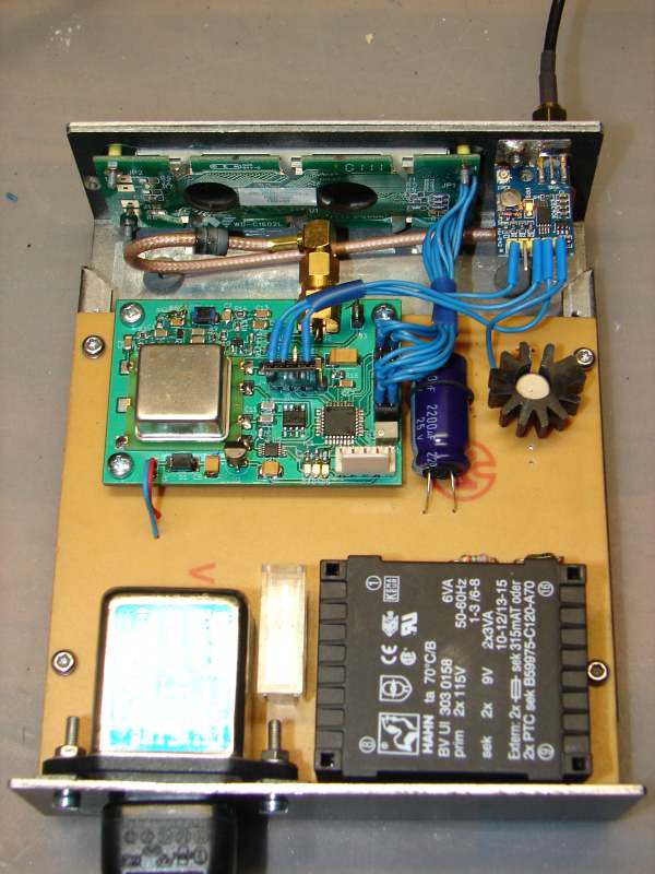
Closed box
SOUTEZ UKONCENA
Download section
Project files - MCU firmware, KiCAD project
Additional informations - datasheets of components etc.
73 OK1DX