RF probe - sniffer
The Radio Frequency probe is a very simple probe used to indicate RF signal level over wide range of frequencies. It uses smart IC Analog Devices AD8307 - logarithmic detector. It should work with gurateeed accuracy up to 150 MHz but can be used up to 500 MHz. The dynamic range should be more than 80 dB, maximum input level about 10 dBm (that means we can measure level -70 dBm = 10 pW!)
There are lot of similar designs published already. The basic design is always the same: RF signal comes into IC and there is a voltmeter like circuit at the output. Some people use analog meter to show the value - fine, but because of too wide dynamic range you will not notice small changes in level / the reading is not accurate sufficiently. Other people put the voltage signal into AD converter of single chip microcontroller - it is much better, the controller can handle also other tasks like calibration and correction of measurement. But it is more complicated solution... I have selected something inbetween: I use already made voltmeter module that is videly available (eBay or so) and cheap. It was designed to measure DC voltage between 00 and 99.9V - I have bypassed an input resistor to increase its sensitivity). The disadvantage is that it is impossible to calibrate the displayed value, so the device is msotly just indicator - it allows to compare signals and there is sufficient resolution (about 0.7 dB) to notice small differencies in signal level (so for example it can be used to tune some circuit to maximum signal).
I have thought some time how to supply the probe. When I use the batteries the probe will be large (and I don't like batteries - must be replaced time to time / esp. when I forgot to switch the device off), to use 230V AC means I need a transformer that makes it big too... So best way would be to use some wall adapter. OK, but ever better to use widely available adapters that give 5V DC in USB socket, used as chargers for MP3 players or so!
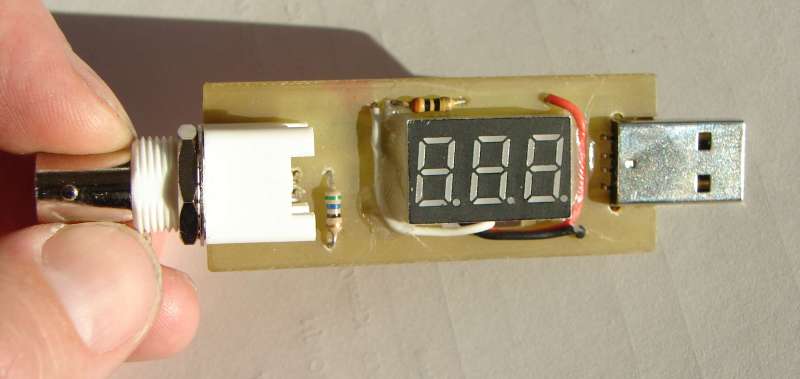
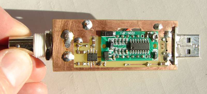
Here is the protype...
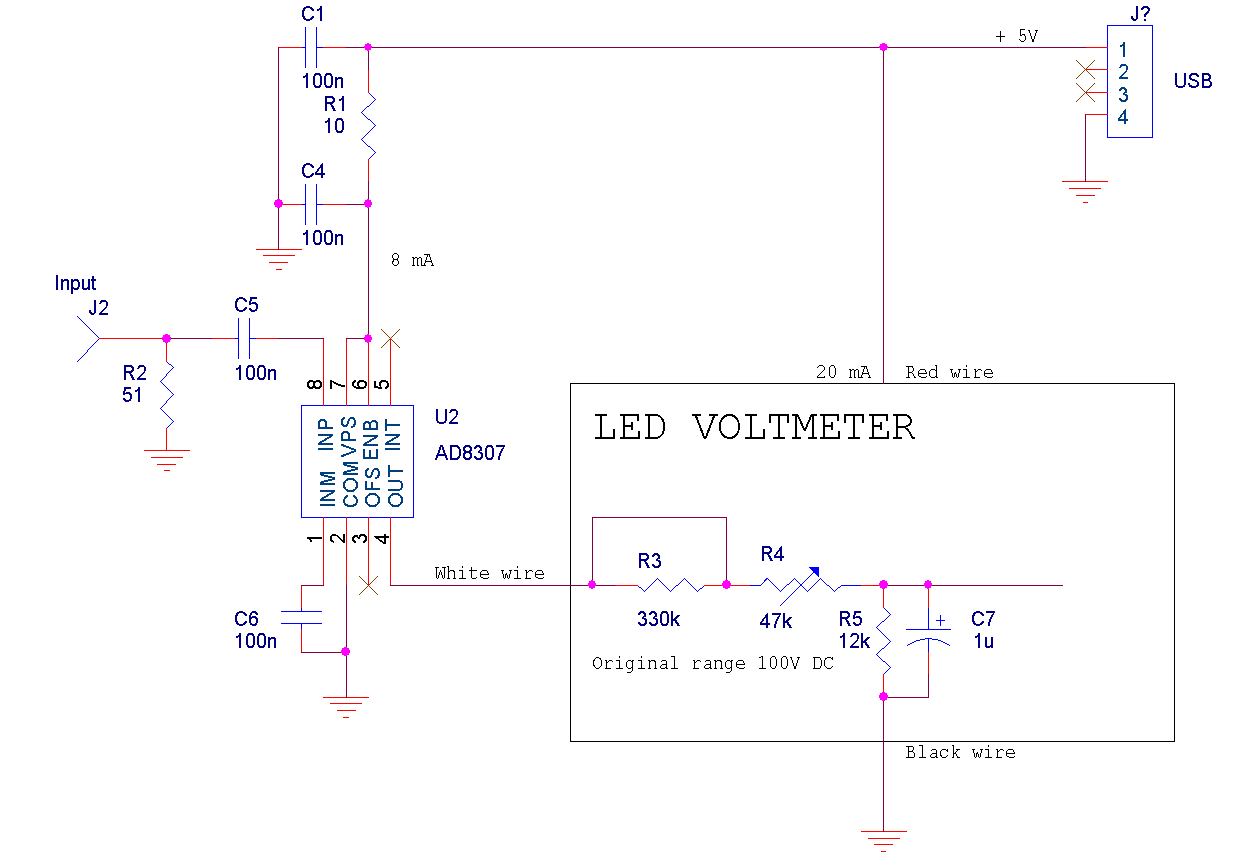
Here is the circuit diagram...
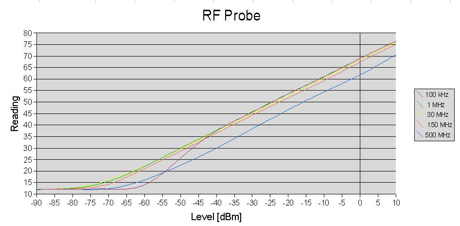
Here is the sensitivity curve (for different freqencies)
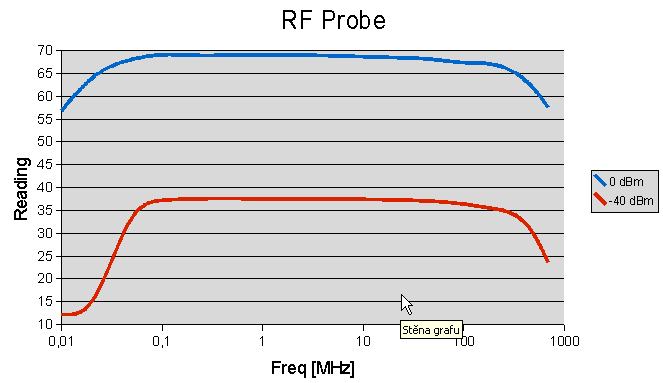
And here is how the sensitivity depends on frequency (for 2 signal levels)
Here's the PCB design for ExpressPCB.