Repair of VHF / UHF transceiver Wouxun KG UV920
I have purchased 2nd hand VHF / UHF transceiver Wouxun KG-UV920 recently. During first test I discovered interesting "feature". When I start transmitting, the RF power comes with about 4 seconds delay, that is of course not acceptable. So I opened the box and started searching for the reason. The circuit diagram for this radio is not availabe on internet. I tried to ask manufacturer directly for some documentation - they just recommended me to give the radio to repair service (OK, when my car is broken, I give the car to service, but because I am RADIOAMATEUR, I MUST first try to do it on my own - fortunately there are still enough radio manufacturers that deliver circuit diagram or make it available - but not the Wouxun). Anyway, they gave me later some tip... Finally, I found the service manual on internet (but when the work was already done). See here.
So I investigated further. I found the RF signal is available immediately up to exciter stage, but it is delayed at drain of exciter MOSFET (Mitsubishi RD07MVS1). The DC voltage is present, so the only reason can be the transistor itself. The MOSFET is very nice part - SMD chip, able to give up to 7W up to 520 MHz (see datasheet). There is just one "problem". Because it is SMD, all soldering pins are located at bottom side, no access with soldering iron possible. I tried to solder gate and drain, with only result - the radio stopped transmitting completely :-)
Next logical step was transistor replacement. I bought spare on eBay, after one month I got it for reasonable price.
So now how to remove the old transistor? Not an easy task. There is a heat sink located at bottom side of PCB, that cannot be removed easily (don't try it!). To experiment with soldering iron can lead to only one result - damage to PCB. I got a good tip from Petr OK1PZ - to use milling machine to completely cut off the faulty transistor. I used a small hand model (similar to that some people use for drilling holes to PCB). Result was perfect, I removed the transistor "by parts" till I got down to PCB.
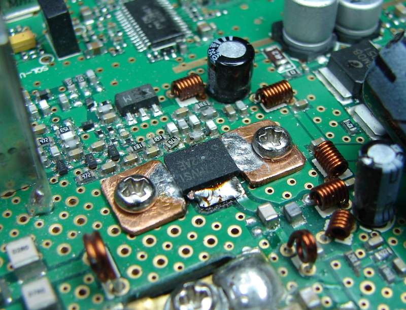
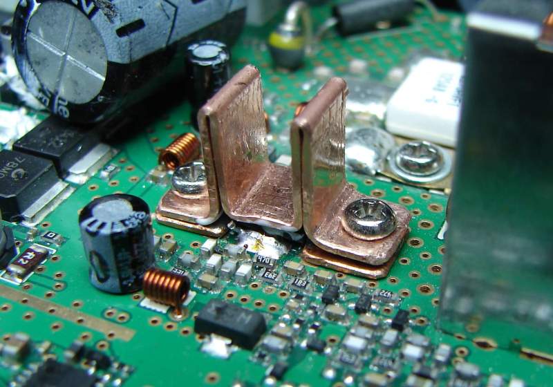
Now how to solder a new one. I haven't try it, based on former experiments. Instead of that I prepared small base plate from copper 0.8mm. So I soldered the transistor to that plate and plate later fixed to PCB by screws. The pictures are better than long explanation. Of course, cooling is worse that it was before, so I prepared a small additional cooler from the top.
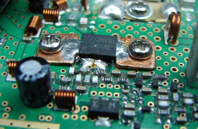
Before I tried to solder the transitor to copper plate I tried to put some small amount of tin to gate and drain as well. And here I discovered what was probably the reason of failure - the pins didn't want to accept tin, they did it after same time only when I repeatedly touched the pins by iron and tried to remove some impurity. I can easily imagine if the original transistor was the same quality that the soldered connection was wrong and the contact was established only after short time when the transistor was heated!!! So because of that, we can expect that similar problem can happen by more pieces for UV920 - thats the reason I write about it here. So, before you finally solder the transistor, clean the pins carefully and be sure pins can accept tin!
Programming tool (not tested) for KG UV920P is here
73 OK1DX