Ultraviolet LED light for PCB production
For long time I prefered old fashioned manual PCB process - to paint the connecting lines directly on PCB material using pen. After color drying the board is etched.
Unfortunately the new SMD technology forced me to manage also photo process, using UV light sensitive photoresist. As part of it I need an intense ultraviolet light that has constant flux over the whole size of the PCB. Once I saw an Ebay offer - 1000 UV LED's for price slightly above $20. So worth to try... Here you can see the result:
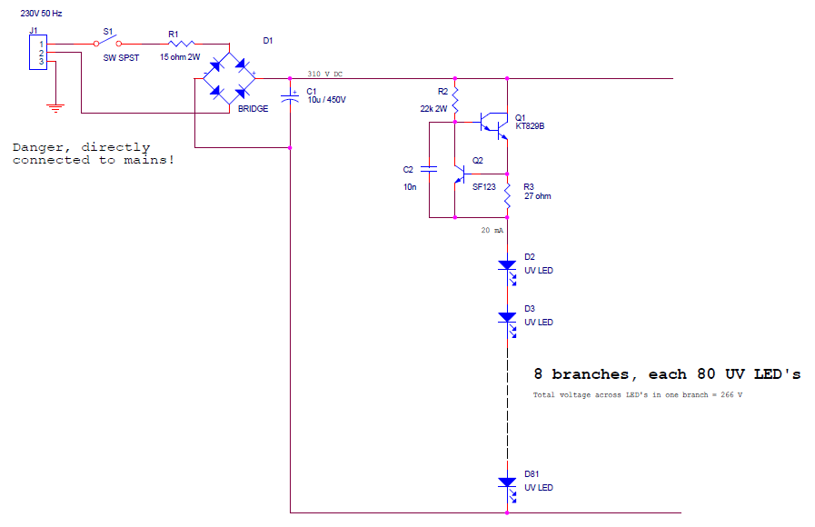
Circuit diagram
Having sufficient number of LED diodes I considered different possibilities how to realize connection and power supply. By 20 mA current the voltage drop across one LED is slightly more than 3V. My decision was to connect 80 LED's in series that results in drop around 270V. If I use a rectifier connected directly to 230V mains it requires some resistor in series that consumes about 40V, radiating about 1W of heat. But instead of classic resistor I decided to use a transistor current stabilizer (enough in my shelf for free) - at least it guarantees the same current when the LED's become hot or mains voltage fluctuates. I decided to use total 8 such branches, resulting in total number of 640 LED's. Here you can see the circuit diagram (just one branch shown).
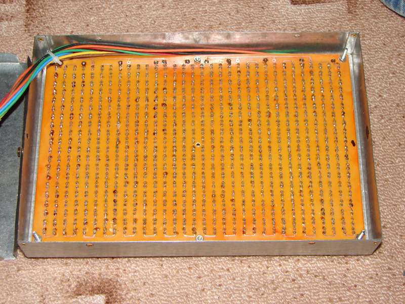
The front part is just a PCB with lot of LED's (you can count how many pins to solder and drill if you like). The LED spacing is 7.5mm (LED dia 5 mm), the total raster is 20 x 32 LED's (connected 20 x 4 x 8).
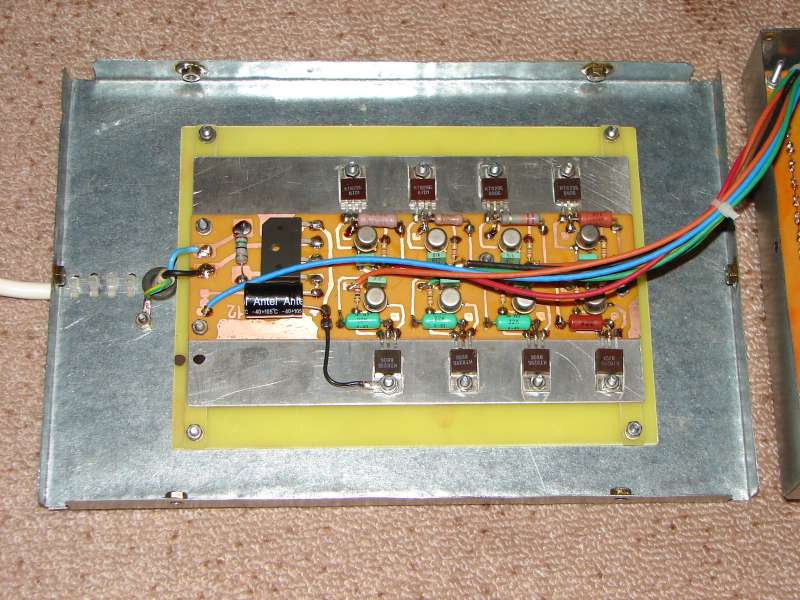
The back side is a cover holding PCB with rectifier and 8 branches of current stabilizers, located on a heat sink. Be carefull, all circuitry is connected directly to mains and therefore has to be well insulated!
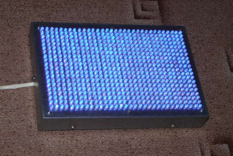
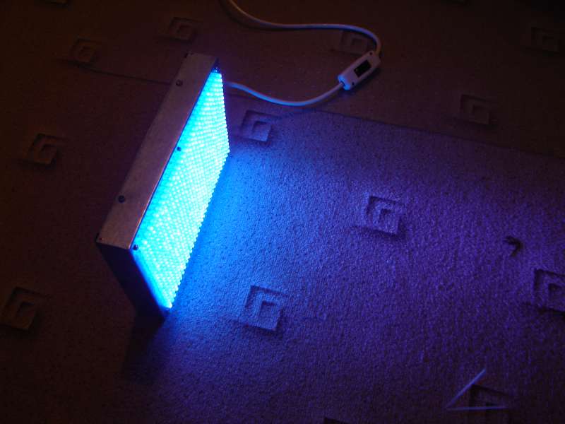
Here you can see the result - a nice blue light...
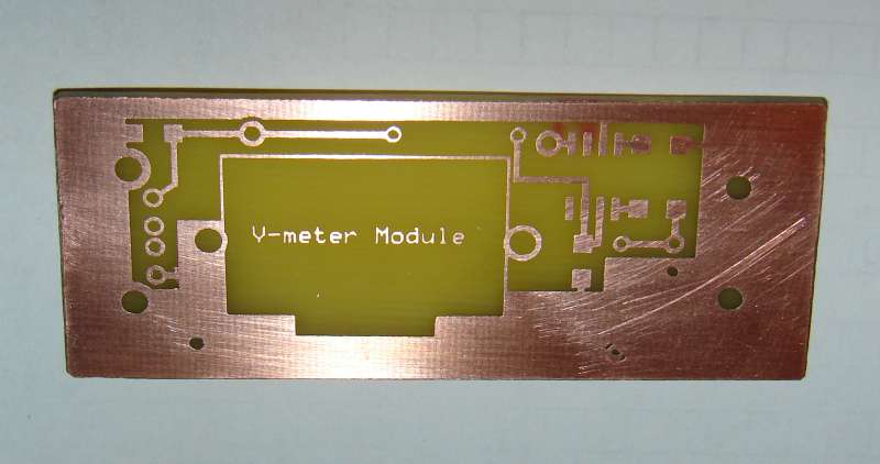
Here is the very first PCB - 3 minutes exposition from 20 cm distance.
73 OK1DX