Main features:
I don't expect anyone to build an own clone, but I think it is worth to mention some details that could be interesting for HAM technicians.
The power level - QO100 is very sensitive satellite, so it is not necessary to overload it with a strong signal, especially on CW. Of course it is necessary to have an efficient antenna
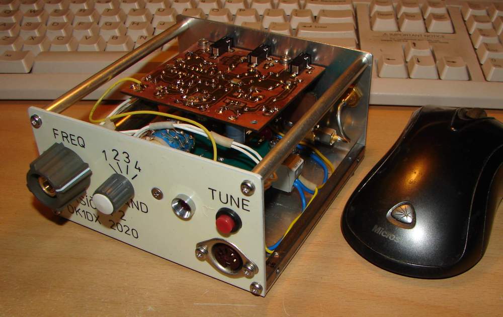
- in my case I use a 80cm offset dish with homebrew 4 turn helix feed. In that case the 100 mW power is sufficient for reliable CW QSO, of course it is good to have a small reserve.
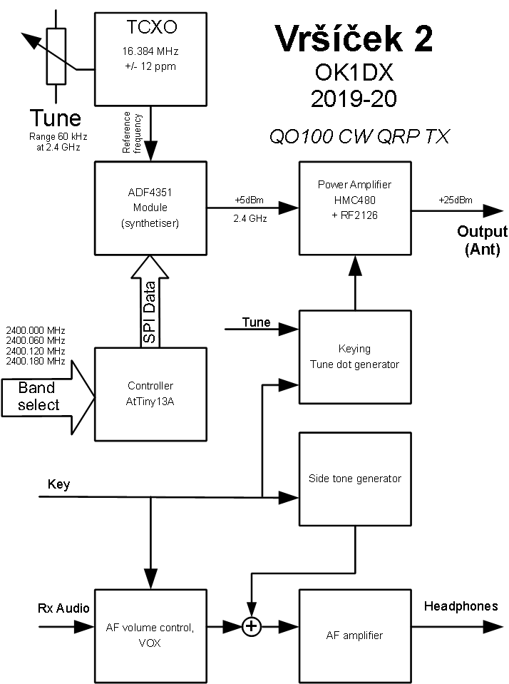
TCXO - using this component you can achive good frequency stability, even immediately after switching power on (it is not true for my 13cm transverter with standard Xtal oscillator
that needs several minutes to settle). I use a TCXO model used in dismounted BTS radios (thanks OK1MHK). The tuning range is not very high - about 400 Hz on 16 MHz, but after multiplication
it results in about 60 kHz coverage on 2.4 GHz.
The tuning potentiometer - must be a precise multiturn (usually 10 turns) to achive fine tuning (about 6 kHz per turn).
The synthetiser uses Analog Devices chip ADF4351. It contains VCO in GHz frequency range, PLL circuitry and dividers for both VCO and reference frequency. The VCO divider support
fractional division ratio that allows to use a small frequency step, that we need to cover more that 60 kHz range of TCXO. The synthetiser must be parametrised upon startup and
after each band change from MCU.
Microcontroller (MCU) is a small cheap Atmel AtTiny13. It has an easy task: read the band selector (using voltage from divider and analog to digital convertor on chip) and send
configuration data to synthetiser via serial interface. I use 4 bands, that differs by counter divider values only, to get the required frequency. There is a tool from AD allowing to
calculate the parameters (see link bellow), so you don't need to hard calculate the registers if you choose another frequencies.
Power amplifier (better say very low power amplifier) increases the ADF4351 signal level to level sufficient for CW QSO. Btw, I tried to connect to antenna just ADF4351 barefoot, the signal was very weak
but the line in spectrum was evident!!! The RF2126 chip is available on eBay very cheap.
The audio part. It is made little bit differently than we are used by conventional radios. The side to generator is necessity despite the fact you can hear your own signal from
satelite's downlink. Problem is the latency - delay the signal needs to pass the distance to satellite and back (plus other possible delay), that can be more than 200 msec.
If you use it with an elbug you will be out of sync for sure. When the key is down the RX audio should be completely muted in order not to disturb the sidetone. But as soon you release
the key you can listen to your own signal that is comming back (something like verification it works). In this case the AF is just partially open (reduced volume) in order not to
disturb the sidetone. But if you finish with your transmission the AF returns to full volume. So there is something like VOX that regulates the RX audio volume.
Dot generator.In order to tune exactly to partners frequency we need to emit the signal and change the frequency precisely. Of course you can use you key, but the sidetone as described above will
interfere. For this purpose there is a tune button that sends dots as long as the button is pressed without sidetone generation and RX audio level reduction. So you can listen to your
downlink signal without any obstacles...