LF DDS - Low frequency Direct Digital Synthesizer project
Last update December 20, 2014
Just to play / test performance of Atmel AVR chip. The heart are few lines of code, that generate DDS sine wave (that means, implement phase accumulator, sine ROM table and sent the result to DAC). DAC is the simplest possible - R/2R network, connected to 8bit port of AVR chip. All that functionality takes just 10 clock cycles, allowing "DDS clock frequency" to be 1.6 MHz by 16 MHz AVR clock crystal. The main limitation of design is clear: the processor is not able to handle user interface (setting freq, display) while sine wave is generated (all CPU power is used for DDS process). This should not be a problem when the design is used as VFO for CW TX, but to use it for RX VFO can be difficult. In other words: as long as the key is down, you cannot change a frequency.
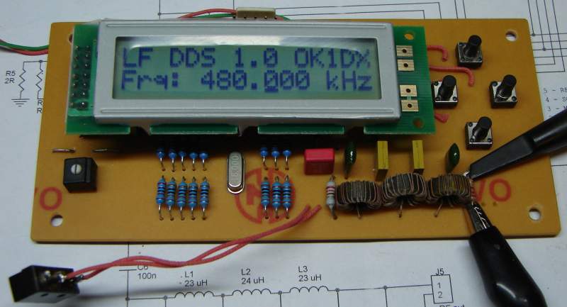
The rest of program just cares about user interface. There is a LCD display, indicating frequency with 1 Hz resolution (the real max resolution is much higher - phase accumulator length is 24bits), 4 buttons (cursor left/right and increase/decrease value).
The sine table is saved in EEPROM and copied at startup to SRAM for faster access. Some other parameters are stored in EEPROM as well (default frequnecy and frequency borders). Default frequency is auto saved to EEPROM after 1 minute without any freq change, for next power up. This feature is here to prevent too many write cycles to EEPROM.
Features
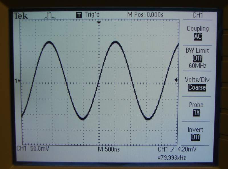
Output frequency up to about 500 kHz (above 600 kHz alias can be a problem). Assumed for 136 and 500 kHz HAM CW transmitters.
High stability (derived from crystal clock oscillator of AVR)
LCD display indicating frequency with 1 Hz resolution (I found 2x16 chars model in my shack, so I use it).
Tuning using UP/DOWN buttons with autorepeat feature. Selected step is indicated by display cursor, cursor can be moved LEFT/RIGHT.
Configurable parameters are stored in EEPROM (band borders, default frequency).
Last used frequency is saved to EEPROM (with small time delay) for next startup.
Output signal is clean enough to be used for amateur transmitters.
Processor can be programmed "in circuit" using dedicated connector. Simple cheap programmer can be used.
Extremely cheap design, usually bellow 10 USD.
Generated signal
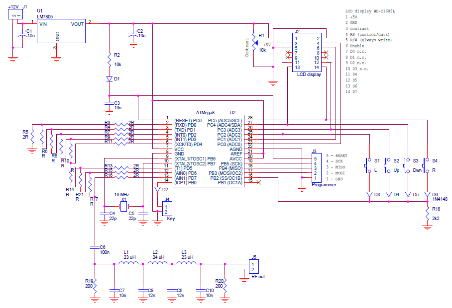
Hardware description
Controller chip is Atmel AVR AtMega8 running at 16 MHz (datasheet maximum). It is not the latest model, advantage is it is widely available in DIL package and it is cheap. Of course, if necessary, some newer AVR chip can be used as well with minimum effort for porting. But Mega8 can still fulfill its duties as needed, and there is still enough space to extend the program (flash memory 15% full).
The output sine signal is generated using 8bit port and R-2R resistor network (R=1 kOhm). The resistors used should be precise (1% accuracy is appropriate - no problem these days).
LCD display is connected in 4bit mode, write only mode (in order to spare pins).
Circuit diagram
Printed circuit board

Firmware description
The program has been completely written in AVR assembler, can be compilled by AVR studio (I use version 4 - see tools at my web; available for free). You can find the sources and binaries at this page, you can download them and use for non commercial purposes for free (Hamware). You can modify the sources as you like, just please keep indication of origin. Commercial use only with author's approval!!!
Project files
73 OK1DX